Gigatron emulation

Discussion of chess software programming and technical issues.

Moderators: hgm, Rebel, chrisw

mar
Posts: 2554
Joined: Fri Nov 26, 2010 2:00 pm
Location: Czech Republic
Full name: Martin Sedlak

Gigatron emulation

Post by mar »

In order to avoid polluting HGM's thread, I created a new one.

I used Marcel's emulator code and I'd like to add audio and controller support.

So I've a couple of questions:

1) what's the colour palette for Gigatron? it has to be fixed 64-entry palette, so either a RGB table or an algorithm to compute the colours would be nice to know
2) how's audio handled? from what I understood, it should probably simply set accumluator somewhere per horizontal line which will be sent to DAC(s), no idea how all 4 channels are handled and how many bits per unit (assume linear samples?)
3) how's input handled? I've no clue here

this is what I have so far, don't mind the wrong colours:
Image

The only drawback is that the emulator needs OpenGL 2.0 compatible GPU (lowend today but Intel GMA won't do), but I can maintain 60Hz and (on Windows) even GPU vsync, so the scrolling is actually smooth.
User avatar
hgm
Posts: 27789
Joined: Fri Mar 10, 2006 10:06 am
Location: Amsterdam
Full name: H G Muller

Re: Gigatron emulation

Post by hgm »

The palette is such that each pair of consecutive bits specifies a primary color, at 0, 33%, 67% or 100% intensity. The two lowest bits are for red. (And I suppose the next two bits green, but I ever actually verivied that with Marcel.) There are simply resistors R and 2R conecting the output bits with the VGA pin for that color, to make a 2-bit DAC.

The sound comes from the XOUT port, which is clocked by a SYNC bit of the OUT port. For the rest I think it is purely a software matter; the interpreter would send new output to XOUT every HSYNC pulse (so at 31kHz). I have no idea how it decides what to send.

The input is complex. It seems to be a shift register, clocked by the HSYNC output of the video OUT port. It seems that game controllers are such serial devices, and need to receive a parallel-load signal to get their button states in their shift register. This parallel-load signal is sent to them from the VSYNC pulse. So 8 scan lines after the (end of?) VSYNC the full button info would be readable from IN. No idea how the bits are assigned to buttons.
mar
Posts: 2554
Joined: Fri Nov 26, 2010 2:00 pm
Location: Czech Republic
Full name: Martin Sedlak

Re: Gigatron emulation

Post by mar »

hgm wrote:The palette is such that each pair of consecutive bits specifies a primary color, at 0, 33%, 67% or 100% intensity. The two lowest bits are for red. (And I suppose the next two bits green, but I ever actually verivied that with Marcel.) There are simply resistors R and 2R conecting the output bits with the VGA pin for that color, to make a 2-bit DAC.

The sound comes from the XOUT port, which is clocked by a SYNC bit of the OUT port. For the rest I think it is purely a software matter; the interpreter would send new output to XOUT every HSYNC pulse (so at 31kHz). I have no idea how it decides what to send.

The input is complex. It seems to be a shift register, clocked by the HSYNC output of the video OUT port. It seems that game controllers are such serial devices, and need to receive a parallel-load signal to get their button states in their shift register. This parallel-load signal is sent to them from the VSYNC pulse. So 8 scan lines after the (end of?) VSYNC the full button info would be readable from IN. No idea how the bits are assigned to buttons.
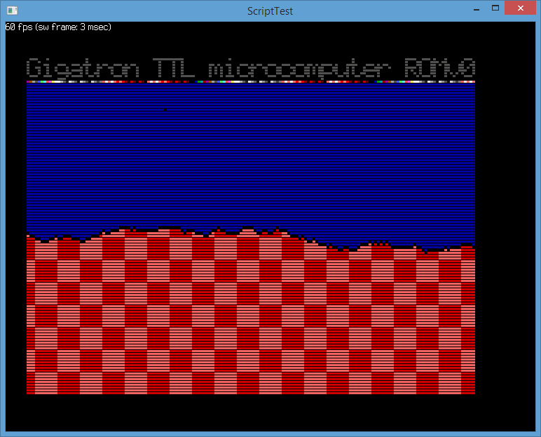
Thanks, I already figured out that it's probably RGB222 and indeed, it seems to work.
So simply iterating 4 times and doing this: ch = ch | (ch << 2) | (ch << 4) | (ch << 6) seems to do the trick to map to the 0..255 range.
Again a nice and simple solution from Marcel.

I've no idea how to access XOUT though as the original emulator only has OUT register (and no idea how the sample is encoded as it should have 4 channels from what I've read).
2 bits per channel don't seem enough I think, but even if it's only 2 bits per channel, one could use all 4 to generate a single 12 level output:
3 + 3 + 3 + 3 = 12
3 + 3 + 3 + 2 = 11 and so on

I've also noticed Gigatron has 4 LEDs that can be probably controlled by the program as well, so emulating those would be nice also. I guess I'll have to wait to get more information on how exactly the audio, controller and LEDs work.

In the meantime I'll try to prepare and upload this unofficial emulator, in case someone would be interested to try it.
User avatar
hgm
Posts: 27789
Joined: Fri Mar 10, 2006 10:06 am
Location: Amsterdam
Full name: H G Muller

Re: Gigatron emulation

Post by hgm »

Marcel was so kind as to give me the schematics, (but I am mot supposed to spread them around). I could deduce from them most of what you want to know, though. First of all, I can confirm bits 2 and 3 of OUT are indeed for green. The XOUT port is an 8-bit register, and the clock input is connected to OUT6, the HSYNC pulse. On a rising edge of OUT6, XOUT is loaded with the content of the accumulator. So not the output of the ALU, which feeds into the OUT (and X and Y) register. So the method to load XOUT is first load the data into the accumulator, and then cycle OUT6 low and high bypassing the accumulator (e.g. using an immediate operand, LD $80,OUT; LD $C0,OUT).

Bits 0-3 of XOUT control the LEDs (high = on). Bit 4-7 feed into a 4-bit DAC (a ladder network of resistors), and then through a band-pass filter to the output jack. So there really is only a single audio channel. The 4 channels you are talking about must be software constructs, added to each other before being sent to the 4 highest bits of XOUT, just before the end of a video HSYNC pulse.
mar
Posts: 2554
Joined: Fri Nov 26, 2010 2:00 pm
Location: Czech Republic
Full name: Martin Sedlak

Re: Gigatron emulation

Post by mar »

Thanks so much for explaining how XOUT works!

Download link: http://www.crabaware.com/Test/gigatron_emu.zip
Please see readme.txt for details.

The emulator is written in a scripting language so it can be modified (fixed) easily.

Binaries included: Windows (32+64 bit), Linux (only tested in a virtual machine) and OSX

Thanks for the clarifications about XOUT, I'll probably add it in the next version.

Sound output is crappy and I've no idea if it's correct at all, LEDs seem to work.
Rémi Coulom
Posts: 438
Joined: Mon Apr 24, 2006 8:06 pm

Re: Gigatron emulation

Post by Rémi Coulom »

Thanks Martin!

I wonder if the flickering would be visible if, instead of displaying 3 lines out of 4, each line is displayed 3 frames out of 4. This could be done in an interlaced way. Or simply skip one full frame out of 4.

Rémi
mar
Posts: 2554
Joined: Fri Nov 26, 2010 2:00 pm
Location: Czech Republic
Full name: Martin Sedlak

Re: Gigatron emulation

Post by mar »

Rémi Coulom wrote:Thanks Martin!

I wonder if the flickering would be visible if, instead of displaying 3 lines out of 4, each line is displayed 3 frames out of 4. This could be done in an interlaced way. Or simply skip one full frame out of 4.

Rémi
From what I understand, interlacing is controlled by the program residing in ROM.
The OUT register controls colors and also signals hsync and vsync.

So one could actually use interlacing not every 4th line but every other line, giving the program more time to think.
Another trick is to only use say 2/3 of the left part of the screen (or center it).

So what might work would be to interlace with not black but some gray colour to make it appear brighter.
Square selection might then be done by making square parts brighter on those "dark" interlaced lines; this wouldn't affect displaying the board itself at all (say even lines = board, dark lines = interlaced dark + selection).
User avatar
hgm
Posts: 27789
Joined: Fri Mar 10, 2006 10:06 am
Location: Amsterdam
Full name: H G Muller

Re: Gigatron emulation

Post by hgm »

Alternating light and dark frames was something that did not occur to me yet. I already experimented with what would happen if you would display only 1 out of 4 lines, rather than 3 out of 4. This still gives a very nice recognizable board image. Having the board brighten up by switching to 3-out-of-4 display when the computer is done thinking is actually a very cospicuous warning signal that it now is your turn.

With 1-out-of-4 display the video only uses 72 out of 520 lines, i.e. 14%. Alterating with dark frames would reduce that to 7%. That should be good enough.

The most annoying thing is that even on black lines the program needs to keep track of the number of cycles it uses, and generate the sync pulses in time. That easily costs more than 14% performance, and an annoying amount of programming effort.
mar
Posts: 2554
Joined: Fri Nov 26, 2010 2:00 pm
Location: Czech Republic
Full name: Martin Sedlak

Re: Gigatron emulation

Post by mar »

I think I understand now the advantage of what Remi proposes.
This way say each other frame would be dedicated for thinking (and say black),
so it might be possible for the engine to avoid any synchronization except for rough approximation of ellapsed time.

I wonder if it would be possible to just run the engine for some time (still need to count cycles but only with a rough precision) and then fake all the hsyncs quickly in sequence before signalling vsync (if that's technically possible, I've no idea).
User avatar
hgm
Posts: 27789
Joined: Fri Mar 10, 2006 10:06 am
Location: Amsterdam
Full name: H G Muller

Re: Gigatron emulation

Post by hgm »

Most monitors lose sync completely if the sync pulses do not come exactly in time, and would take several frames to recover from that. Marcel told me that he had seen a case where an LCD moitor refused to display any image because some of the lines had 1 pixel more than the others.