Several of us played with these things after Ken Thompson started the ball rolling. I don't like the 4 led's. You have to sit at the table normally to see why. They are obscured by some of the pieces. I built four of these things.MikeB wrote:Perfect - 4 LEDs per square , far superior to one LED per square.PiotrWilczek wrote:Hi,
My name is Piotr, it's my first post here
I've build electronic chessboard with bluetooth. It's similar to other electronic chessboards:
- it's using magnetic sensors to detect figures' position
- it's using led lights to show opponent's moves
- it has build in bluetooth module to communicate with external devices (PC, tablets, android and iphone phone etc...)
The difference is that it does not have build-in chess engine, it just sends information through bluetooth about chess pieces positions and control led lights. All chess logic is done in connected device.
Most of you have programming skills so it would be fairly easy to integrate this board with your chess programs and engines. I've done some simple android chess app and I love to play with chess engine on real board.
Here is the demo of how it works: http://32chessmen.com/
I want to keep it open source. I'll explain how it's done and share the code so everyone can build it but I also want to start making them and sell to those who prefer ready product.
I would love to hear your comments and suggestions.
Iteration 1 used 4 lamps (not LED's, they were way too dim back in the 70's). The obscuring problem made them hard to see.
Iteration 2 used one lamp with semi-translucent squares. Real chess players complained that the board didn't look "natural". In a human event, back then, if there was any question, a standard USCF "roll-easy" board had to be used.
All of these were based on a 3/4" piece of plywood, plus that translucent plastic plus the vinyl board surface described above. The 3/4" plywood helped hold the switches securely and properly oriented (eventually).
Iterations 1 and 2 used hall effect transistors which were too finicky for me since I did chess demos all over the world and had to transport this thing.
Iteration 3 was close to the final. Here I used a standard roll-up board glued to a neutral-color (about same color as light squares) translucent panel. I then took a router and very carefully cut a 1/4" hole in the upper right-hand corner of each square, about 1/8" from the two edges. Underneath this I used incandescent bulbs turned on via a darlington-pair power transistor (ask if you are interested in what that is). And for a detector I used a magnetic reed switch, one per square. Edition 3a incorrectly had me rout a small channel in the middle of each square and then lay the switches down. Wrong orientation and this did not work well at all. 3b had me drill a vertical hole in the center of each square and insert the reed switch so it was oriented the correct way. Problem with this one was sensitivity. If you set the piece too far off-center, the switch would not close. But the lights were really optimally placed for the operator (me) since I used this to play speed games against GMs. But we kept having problems with fast moves leaving pieces in a position where the switch was not closed.
Final version (4) had 4 reed switches per square, sort of uniformly spaced. With 2 1/4" squares, which was the normal tournament size back then, if you center a 1" square in the middle, I drilled 4 holes at the 4 corners of that and used 4 reed switches. If one was closed, that was good enough and this allowed off-center pieces just so they did not overlap onto adjacent squares (which is illegal anyway).
Only flaw with my design was it could not "read" a position, either square was either occupied or empty. But piece moves were easy. For rooks/bishops/queens I did a "landing light" approach where I turned on the source square, then the next, then the next, with a small delay to create the well-known "chasing" effect. When the destination was turned on, then the source was turned off, and then each square in that direction was turned off until the pattern repeated. To avoid a burned out bulb screwing me up, when Cray Blitz made a move, the lights would flash until the source was empty AND the destination was occupied. If the destination light was burned out, the lights would keep flashing if I landed one square short letting me know. There are a couple of quirks dealing with capturing and castling, but they were easy enough.
I took a standard set of USCF Staunton pieces that were weighted, and removed the weights (easy to do, remove felt, the pry it out). I then filled piece with automobile bondo, and pressed in a ceramic disc magnet and let it cure. Reglued the felt and I was done.
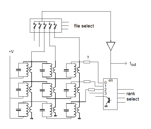
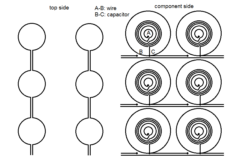
Ken Thompson went one further. He put loading coils in the base of his pieces, similar to my magnets. He then had horizontal wires running under the squares (which were receiving antennas) and vertical wires running under the squares as well. He would inject a specific frequency for the piece type he wanted to locate, and scan each rank in succession. The loading coil would couple the transmitted signal to the receiver antenna and he would get zeroes and ones, ones where the piece type being scanned for sat.
He also used the light under the whole square, but then he didn't try to use his board in real tournaments, where we used ours in a US Open speed chess championship tournament and had to have something that was not too different. A couple complained about the small circles, but they were only visible on the green squares and the TD decided it was not THAT annoying.
If you are designing a board for viewing from all angles, 4 less are probably the best design. If you design it to be played from either side, 2 or 4 is again OK. But for me, 1 was the right number since I always sat on the same side of the board. Gave me max visibility with min irritation to opponent. I still have this old board in my office, but it hasn't been connected up in 25 years at least.
The newer DGT approach is cleaner from the detection perspective, using RFID chips for each piece type. But the one I have had had no LEDs to indicate moves. Good for recording / relaying games, not so much for playing games against a computer...
I even built an electronic chess clock using capacitive touch switches for the two buttons (TTL cookbook recipe). Interfaced to the computer also so that CB never had to ask about how much time was left, it could read the values instantly...
I remember playing in a tournament (ACM) with Kathe Spracklen. My board used a z80 back then to do the scanning and handling das blinkenlights, and she commented "Bob, you have more computing power in your board than I have for my program."
Later on I became quite famous for my blitz chess typing abilities, in that we used to take on all challengers using a real clock, a real chess board, with me operating. Over a 5 year period, I think we might have lost 3-4 games (on time). GM Ivanov wore me out one night after an ACM event round, and sat and played speed chess for almost 5 hours, non-stop. Couple of draws, one win on time, the rest CB easily won..
Somewhat off-topic for the chess board issue itself, but that was the reason I had designed the chess board in the first place. I didn't have to type a thing, and didn't have to read the output and figure out what the move was and play it, just watched for blinking lights.
BTW this is not a criticism of this board as shown. Looks really nice and functional. Was more a discussion about best way to show moves. Sharing LEDS among squares does tend to make it a bit harder to recognize moves when you are sitting at a normal position where pieces obscure view of the corners of the squares.